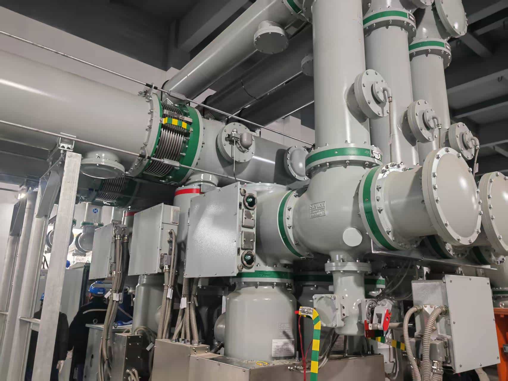
In preventive maintenance of power systems, the circuit resistance tester is an essential instrument. It is widely used for measuring contact resistance of high-voltage circuit breakers, as well as evaluating the connection quality of switches and busbar joints.
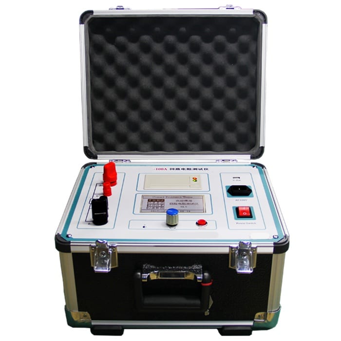
With years of experience in power testing equipment, Baoding Qilida Electric Technology Co., Ltd. has developed the QLDH series circuit resistance testers, known for high accuracy and stability. This article explains the working principle, key technologies, applications, and selection guidelines of circuit resistance testers.
1. What Is a Circuit Resistance Tester
A circuit resistance tester, also known as a contact resistance tester, is designed to measure the resistance of conductive connections in electrical equipment.
Although standard multimeters can measure resistance, they are not suitable for micro-ohm (μΩ) level measurements. Contact resistance is highly sensitive to oxidation, pressure, and surface conditions, which requires high current and high precision measurement.
The QLDH series, including QLDH-100A, QLDH-200A, and QLDH-300A, is specifically designed for such applications and is widely used in substations, power plants, and industrial facilities.
2. Working Principle of Circuit Resistance Tester
The circuit resistance tester is based on two key technologies:
Constant current source
Four-wire (Kelvin) measurement method
The basic process is:
Constant current output → Current flows through the test circuit → Voltage drop is measured → Resistance is calculated using Ohm’s law
2.1 High Current Constant Source
To ensure accurate measurement, the tester outputs a stable DC current.
The QLDH series supports output currents from 100A up to 600A. This high current helps eliminate the influence of oxide layers on contact surfaces, ensuring that the measured resistance reflects real operating conditions.
2.2 Four-Wire (Kelvin) Measurement Method
This is the core of the measurement principle.
The tester uses two separate circuits:
Current circuit (I+ and I-)
Voltage circuit (U+ and U-)
The current circuit injects high current into the test object, while the voltage circuit measures the voltage drop independently.
Since the voltage circuit draws almost no current, the influence of lead resistance and contact resistance is eliminated. This allows accurate micro-ohm level measurement.
2.3 Digital Signal Processing
The internal microprocessor processes the voltage signal through:
Amplification
Filtering
Analog-to-digital conversion
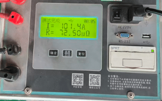
The final resistance value is displayed directly on the screen.
The QLDH series also features enhanced hardware filtering, making it suitable for high-interference environments such as substations.
2.4 Calculation Formula
The resistance is calculated using:
R = V / I
Where:
R is resistance (μΩ)
V is voltage drop (μV)
I is current (A)
3. Why Use a Circuit Resistance Tester
Some engineers may consider using a bridge method instead. However, circuit resistance testers offer clear advantages:
Higher anti-interference capability, suitable for field environments
High current output matching real operating conditions
Faster testing with automated operation
Portable and user-friendly design
The QLDH series is designed with enhanced shielding and grounding, ensuring stable performance in substations.
4. How to Use QLDH Circuit Resistance Tester
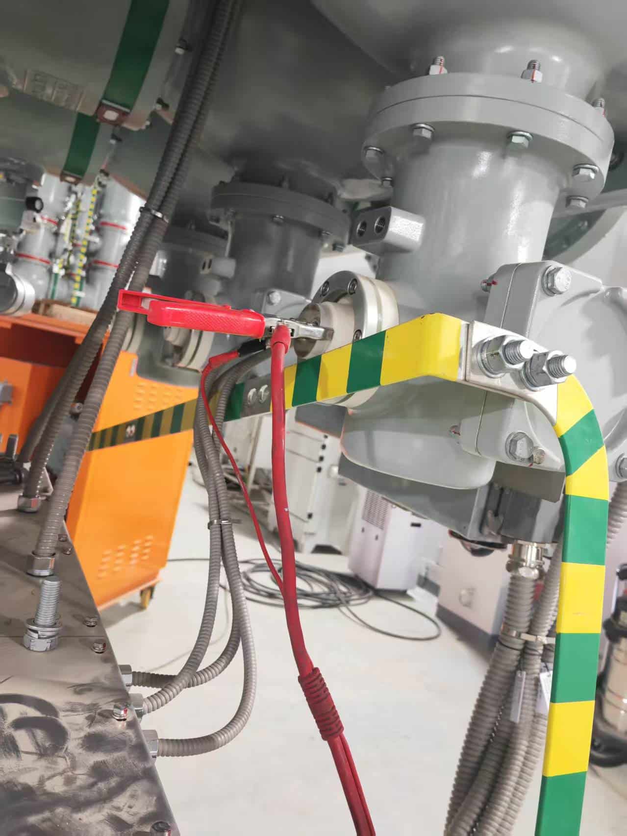
Typical test procedure:
Ensure the equipment is de-energized and properly grounded
Connect current and voltage leads using four-wire method
Power on the instrument
Select the desired test current
Start the test and wait for stable current output
Read and record resistance value
Compare with standard limits
Discharge after test before removing connections
5. Key Features of QLDH Series
Wide current range from 100A to 600A
Measurement range up to 2999 μΩ
Accuracy up to 0.5% ± 3μΩ
Built-in protection against overcurrent, overheating, and open circuit
Data storage up to 200 records
RS232 interface and optional Bluetooth
Large LCD display for clear outdoor reading
6. Troubleshooting
No display: Check power supply and fuse
No current output: Check circuit connection
Unstable data: Clean contact points and check voltage leads
Printer issue: Check paper installation
7. How to Choose the Right Model
For 10kV to 35kV equipment, 100A is sufficient
For 110kV and above, 200A or 300A is recommended
Consider portability for field work
Ensure data storage and communication functions
Choose a reliable manufacturer with testing capability
8. Conclusion
A circuit resistance tester is essential for accurate evaluation of contact resistance in electrical systems. By combining high current output with four-wire measurement, it ensures reliable and precise results.
The QLDH series provides a stable, accurate, and practical solution for preventive maintenance and condition assessment in power systems.
Call to Action
Looking for a reliable circuit resistance tester?
Contact us to learn more about the QLDH series and get professional support for your testing requirements.