A partial discharge detector is a critical tool used to evaluate the insulation condition of high-voltage electrical equipment. It is widely applied in transformers, cables, GIS, bushings, and rotating machines. By detecting partial discharge signals inside insulation, potential defects can be identified at an early stage, helping improve operational safety and long-term reliability.
1. What Is Partial Discharge
Partial discharge is a localized electrical discharge that occurs within a portion of an insulation system. It is typically caused by defects such as air voids, contamination, moisture, or insulation aging.
Although partial discharge does not immediately result in breakdown, it continuously degrades insulation and may eventually lead to serious equipment failure if not detected in time.
2. Measurement Principle of Partial Discharge
Partial discharge measurement methods can be divided into electrical and non-electrical techniques.
Electrical methods are the most widely used and mainly include:
Pulse current method (ERA method)
Radio interference voltage method (RIV method)
Non-electrical methods include:
Acoustic detection
Optical detection
Infrared imaging
Chemical analysis
Among these, the pulse current method is the standard approach for quantitative PD measurement due to its high sensitivity and reliability.
The pulse current method offers several advantages:
It captures detailed discharge information through pulse waveform and statistical patterns such as φ-q-n analysis
It is highly sensitive to transient signals, allowing fast and accurate fault detection
It supports quantitative evaluation of partial discharge magnitude
Non-electrical methods are mainly used as auxiliary techniques due to the lack of standardized quantitative measurement.
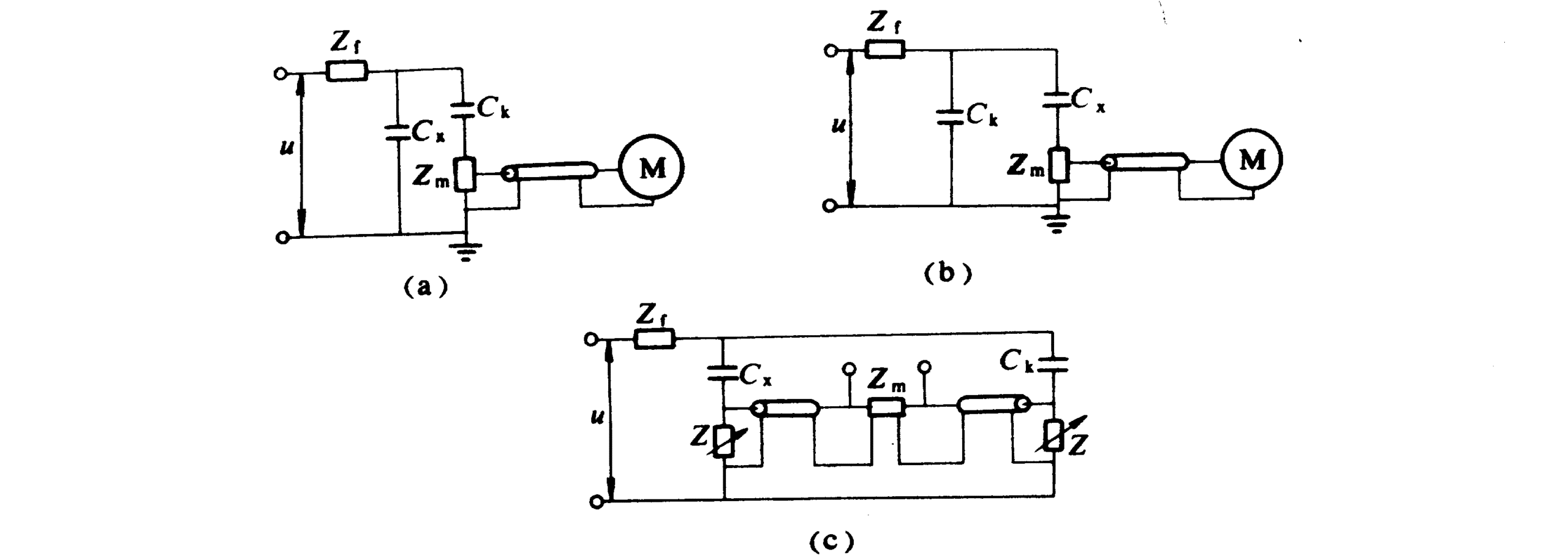
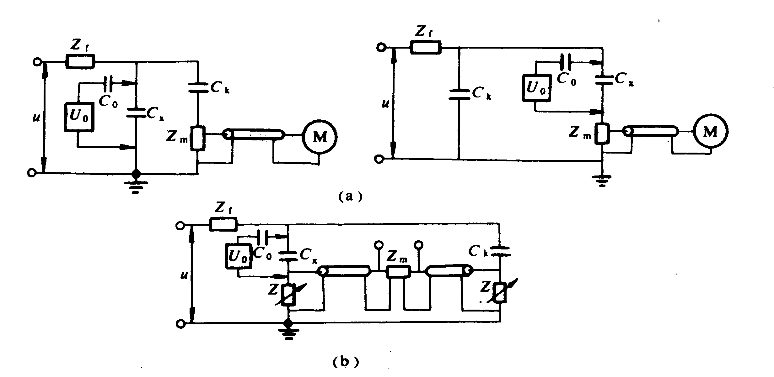
3. Test Circuits and Measurement Methods
The pulse current method typically uses two types of test circuits:
Direct method
Bridge method
The direct method includes:
Parallel test circuit, suitable for large capacitance test objects or cases where grounding conditions are complex
Series test circuit, suitable for smaller capacitance, with coupling capacitors improving sensitivity and suppressing interference
The bridge method uses a balancing principle to eliminate external noise, offering strong anti-interference capability. However, its sensitivity is generally lower compared to the direct method.
4. Signal Generation and Detection
Partial discharge generates very short-duration current pulses, typically in the nanosecond range. Although the signal amplitude is small, it carries valuable information about insulation defects.
Common detection methods include:
Electrical signal detection using coupling capacitors
Ground current detection using high-frequency current transformers (HFCT)
Electromagnetic detection using UHF sensors
Acoustic detection using ultrasonic sensors
Different detection methods are selected based on equipment type and on-site conditions.
5. Signal Processing and Analysis
After acquisition, signals are processed to extract meaningful data. Modern partial discharge detectors perform:
Signal amplification and filtering
Noise suppression and interference rejection
Digital sampling and data processing
Spectrum analysis
Phase-resolved analysis
Among these, phase-resolved analysis is the most important technique for identifying discharge characteristics.
6. Phase-Resolved Partial Discharge Analysis
Under AC voltage, partial discharge activity is closely related to the phase of the applied voltage.
By analyzing the distribution of discharge signals across voltage cycles, different types of defects can be identified:
Internal discharge is concentrated in specific phase regions
Surface discharge shows wider phase distribution
Corona discharge typically appears in a single polarity region
This analysis is commonly presented as a PRPD (Phase-Resolved Partial Discharge) pattern, which is essential for fault diagnosis.
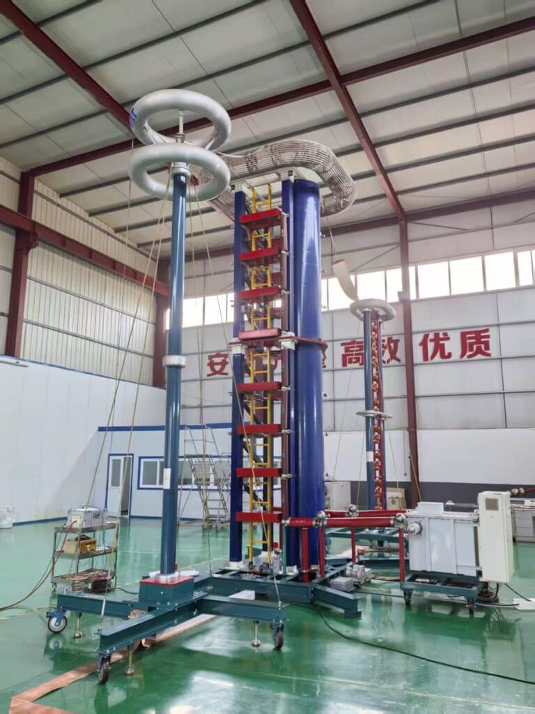
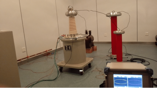
7. Main Components of a Partial Discharge Detector
A typical partial discharge detection system includes:
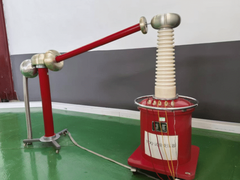
High-voltage power supply
Coupling capacitor
Measuring impedance
Signal acquisition unit
Sensor system
Data processing unit
Display and control system
Grounding and shielding system
These components work together to ensure accurate signal detection and analysis.
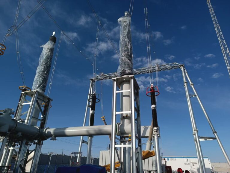
8. Applications of Partial Discharge Testing
Partial discharge testing is widely used in insulation condition assessment for:
Power transformers
Current and voltage transformers
High-voltage cables
GIS equipment
Bushings
Generators and motors
Typical applications include factory testing, commissioning, preventive maintenance, and online monitoring.
9. Importance of Partial Discharge Detection
Partial discharge detection is one of the most sensitive diagnostic methods for insulation evaluation.
Compared with traditional methods such as insulation resistance or dielectric loss testing, PD testing can identify defects at a much earlier stage.
Regular PD testing helps:
Detect insulation defects before failure
Reduce unexpected downtime
Improve equipment reliability
Extend service life
10. Conclusion
A partial discharge detector is an essential solution for early-stage insulation fault detection in high-voltage equipment. By capturing and analyzing high-frequency discharge signals, it provides accurate insight into insulation condition, supports predictive maintenance, and significantly reduces operational risks.