Project Background: Strict Acceptance Standards for New Overseas Substations
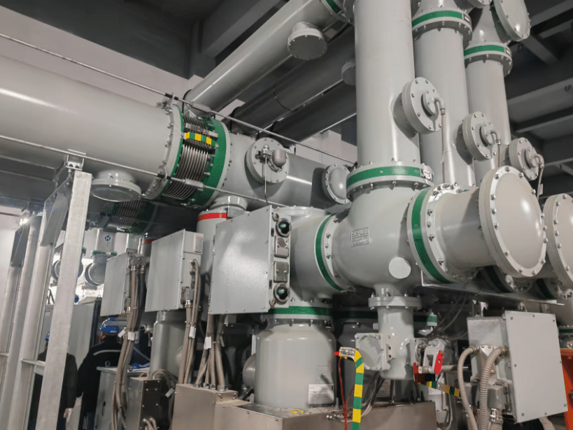
The Zhenshi Indonesia Project is a newly constructed 220kV substation located in a tropical marine climate zone, imposing high demands on equipment reliability and installation quality. As the core of the substation, Gas-Insulated Switchgear (GIS) performance directly depends on the integrity of conductive circuits. According to GB 50150 and IEC standards, the loop resistance of each phase in GIS equipment must be balanced, with all connection points meeting specified resistance limits.
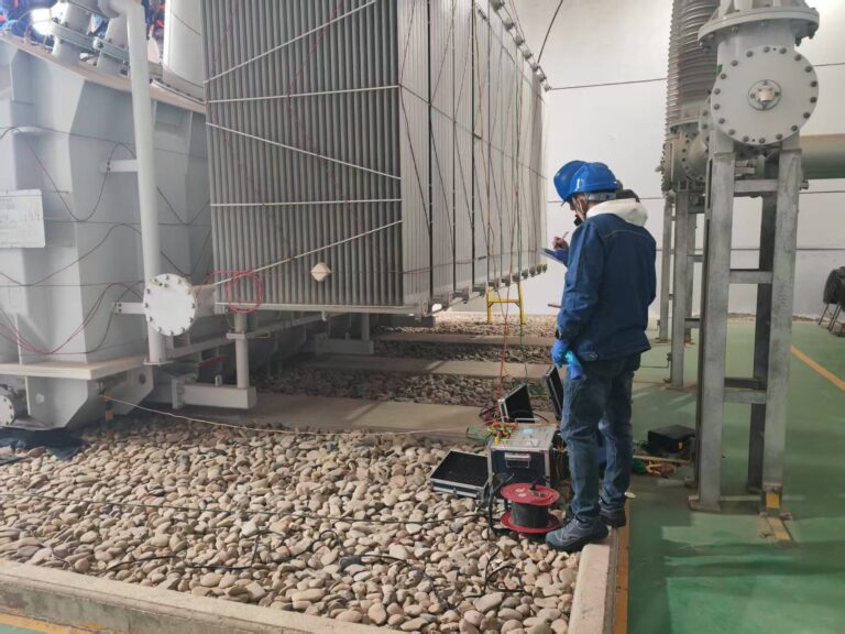
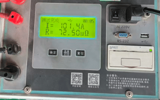
On-Site Loop Resistance Tester(Test)
The project team utilized the Qilida QLDH-5100 Loop Resistance Tester, developed and manufactured by Baoding Qilida Electric Power Technology Co., Ltd., to perform comprehensive circuit resistance tests on GIS switchgear. Testing all three phases (A, B, C) revealed the following:
| Phase | Measured Loop Resistance (μΩ) |
|---|---|
| A | 200 |
| B | 240 |
| C | 198 |
-
Phases A and C showed balanced resistance, while Phase B’s value was significantly higher.
-
The unbalanced three-phase readings indicated abnormal connection resistance in the B-phase circuit.
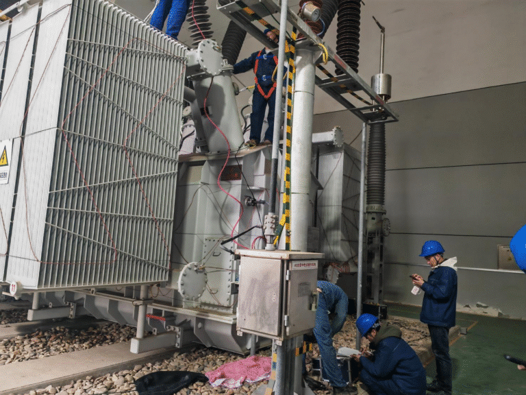
Fault Localization Through Segment Testing
Using the QLDH-5100, engineers isolated segments of the B-phase circuit to pinpoint the issue:
-
External Connections Check: Busbars and terminals were inspected; no abnormalities found.
-
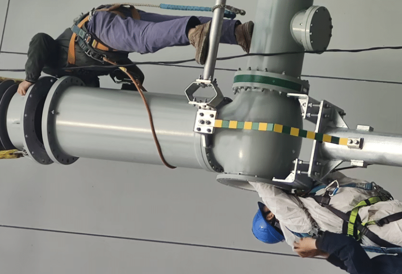
Segment Isolation: B-phase segments were tested individually, revealing potential issues around the GIS bushing.
-
Bushing Standalone Test: Removing the B-phase bushing and testing its loop resistance separately confirmed an elevated value.
| Phase (Bushing) | Measured Loop Resistance (μΩ) |
|---|---|
| A | 38 |
| B | 72 |
| C | 39 |

Problem Identification and Manufacturer Repair
The test results were reported to the bushing manufacturer. Inspection revealed assembly defects in the B-phase bushing’s internal conductive connections, causing increased contact resistance. After repair and process optimization, the B-phase bushing was retested:
| Phase (Repaired Bushing) | Measured Loop Resistance (μΩ) |
|---|---|
| B | 39 |
The repaired B-phase bushing now matched A and C phases, restoring proper circuit balance.
Reinstallation and Full System Verification
The bushing was reinstalled in the GIS device, and a full-loop resistance test confirmed:
| Phase (Full System) | Measured Loop Resistance (μΩ) |
|---|---|
| A | 201 |
| B | 201 |
| C | 200 |
All readings were within standard limits, ensuring safe commissioning.
Key Advantages of QLDH-5100 Loop Resistance Tester
-
High Precision: Detects micro-level differences in the 200μΩ range, supporting accurate fault diagnosis.
-
Reliable and Repeatable: Consistent results across multiple tests, unaffected by environmental variations.
-
Easy to Operate On-Site: Lightweight and simple connection design for complex field conditions.
-
Guides Efficient Fault Location: Segment testing and comparative analysis accelerate problem identification, avoiding unnecessary disassembly.
The QLDH-5100 Loop Resistance Tester proved essential for ensuring the safe and reliable operation of GIS equipment in high-standard overseas substations, providing both accurate measurement and actionable insights for field teams.